
For this experiment, it was necessary to do some adjustments of the equipment. The float switches on the T5552 are in normally open configuration. However, for this circuit, it was a requirement to change them to normally closed. In order to do that, one should look on the top and if it sees writing (manufacturer's name) it is in open configuration. To change its configuration the following figures are shown:
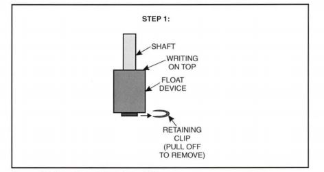
Figure 1. Location of the retaining clip (Process Control Systems, 2010)
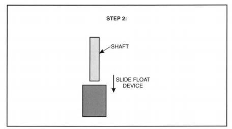
Figure 2. How to remove the float device (Process Control Systems, 2010)
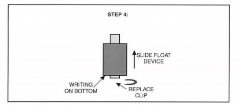
Figure 3. Float device and retaining clip replacement (Process Control Systems, 2010)
Figure 1, 2 and 3 are the precise procedures to start testing the equipment. Then a special arrangement for the circuit was done in order to work on the ON/OFF controller:
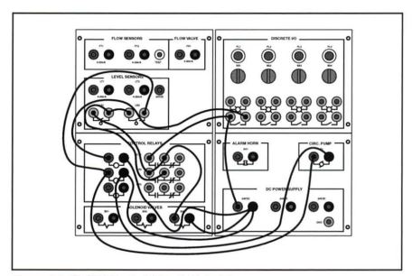
Figure 4. On/off control circuit (Process Control Systems, 2010)
The On/off controller solenoids valves are activated when the set point is surpassed and the level of the water starts dropping. However, if the level of the water is below the set point, the solenoid valves are deactivated and the pump is triggered.
